Why Choose an Industrial Gear Motor for Your Application?

Time:2026-10-02 Author:Amelia
0%

Choosing an Industrial Gear Motor is not merely a specification exercise. It affects torque, energy use, noise, maintenance, and production continuity. In a packaging line, for example, the motor must start a loaded conveyor without jerking fragile cartons. A small mismatch can create heat, vibration, and costly downtime.

The U.S. Department of Energy reports that motor-driven systems consume about 70% of industrial electricity in the United States. That figure makes efficiency impossible to ignore. The International Energy Agency also identifies industrial motor systems as a major efficiency opportunity. Meanwhile, MarketsandMarkets’ recent gear motor research projects continued market growth through the decade, driven by automation, material handling, and process equipment. Numbers help, but they do not choose the right reducer.

Gear-technology specialist Dr. Hermann J. Stadtfeld has emphasized, “The gear is the heart of every machine.” His point remains practical: transmission quality determines how power reaches the load. A helical Industrial Gear Motor may suit a quiet conveyor, while a planetary design can provide high torque in limited space. Environmental details matter too, including washdown exposure, dust, ambient temperature, and duty cycle.

The choice is rarely perfect.

Engineers should compare rated torque with starting torque, not only catalog horsepower. They should calculate service factors, inspect mounting alignment, and verify thermal limits. I have seen promising selections fail because a clean-looking motor faced abrasive dust every shift. Reliable selection combines manufacturer data, site measurements, and honest review of operating habits. That discipline turns an Industrial Gear Motor from a purchased component into dependable production infrastructure.
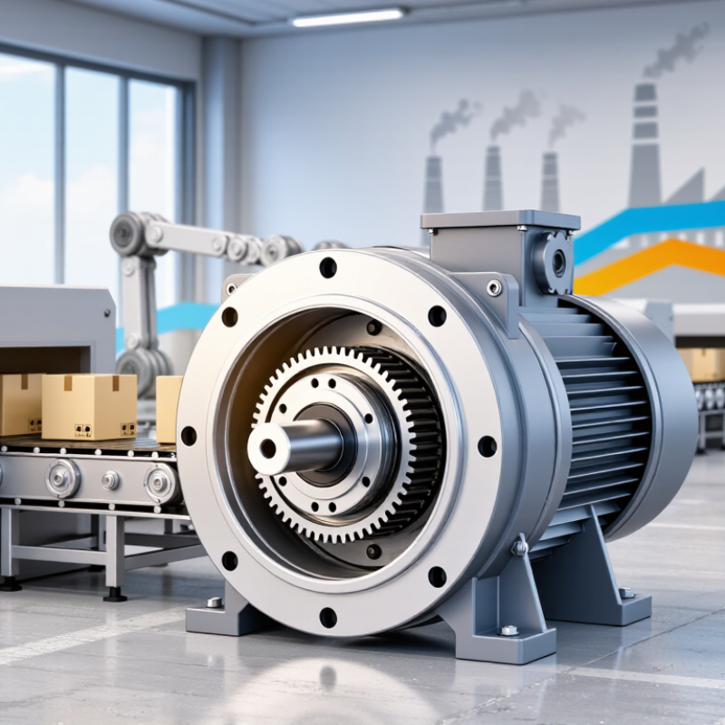
Why Choose an Industrial Gear Motor for Your Application?

What Is an Industrial Gear Motor?

An industrial gear motor is an integrated drive unit that combines an electric motor with a gearbox. The motor creates rotational power. The gearbox reduces speed and increases torque at the output shaft. This arrangement helps conveyors, mixers, hoists, and packaging machines move steady loads without oversized motors.

The gearbox usually contains spur, helical, bevel, or worm gears. Each design changes efficiency, noise, alignment, and maintenance needs. In practical plant inspections, output torque and duty cycle often matter more than rated horsepower. A motor may appear suitable, yet stall during repeated starts. That mistake is common.

Energy use also deserves attention. The International Energy Agency reports that electric motor systems consume about 53% of global electricity. The U.S. Department of Energy states that motor-driven equipment can represent more than half of industrial electricity use. These figures explain why gearbox efficiency, lubrication, and correct sizing deserve careful review. A gear motor is not automatically efficient. Poor alignment creates heat and vibration. In my view, calculations should include starting torque, shock loads, operating hours, and ambient temperature. The calculation is rarely perfect. Real machines can be less predictable than spreadsheets. Even a small service factor may be insufficient for abrasive materials or frequent reversals. A reliable selection process combines manufacturer data, measured load conditions, and scheduled inspection records.

How Do Industrial Gear Motors Transmit Power?

Industrial gear motors transmit power by combining an electric motor with a geared reduction system. The motor creates rotational force, called torque, on its input shaft. That shaft turns a small pinion gear, which drives larger gears inside the housing. The larger gears rotate more slowly, but they deliver significantly higher torque to the output shaft. This controlled reduction helps conveyors, mixers, pumps, and lifting equipment handle demanding loads.

In practical installations, gear ratio determines the balance between speed and force. A high ratio produces stronger output torque but slower movement. Bearings support the rotating shafts, while seals retain lubricant and keep contaminants outside. Proper lubrication reduces heat and tooth wear. From field inspections, I have seen misalignment create vibration, noise, and premature failure. The calculation is rarely perfect. Starting loads, shock loads, and duty cycles can change the real result.

Tips: Check the required output speed, torque, and service factor before selecting a gear motor. Measure the driven load, not only the motor size. Keep shafts aligned and inspect lubricant levels regularly. A slightly oversized unit may improve reliability, but excessive sizing can waste energy and increase costs. Also, confirm that the mounting position matches the manufacturer’s lubrication requirements. Small details matter.

Why Choose an Industrial Gear Motor for Your Application? — How Do Industrial Gear Motors Transmit Power?
Data Dimension Industrial Gear Motor Principle Typical Technical Data How Power Is Transmitted Application Benefit Selection Consideration
Power Transmission Path Electrical input is converted into rotational motion by the motor and mechanically modified by the gearbox. Motor speed commonly ranges from approximately 750 to 3,600 rpm before reduction. Motor torque enters the gearbox through the input shaft. Gear meshes transfer torque between stages, while the output shaft delivers reduced-speed rotation. Provides controlled speed and higher usable torque without requiring a larger high-torque motor. Verify motor power, rated speed, duty cycle, and gearbox service factor.
Speed Reduction The gearbox reduces the motor's high rotational speed to the speed required by the driven machine. Common industrial reduction ratios range from approximately 3:1 to 300:1, depending on gearbox design and number of stages. A smaller input gear drives a larger gear, or multiple gear stages progressively reduce output speed. Supports conveyors, mixers, feeders, hoists, and other machinery requiring controlled low-speed operation. Choose the ratio based on required output speed: Output Speed = Motor Speed ÷ Gear Ratio.
Torque Multiplication Mechanical advantage from the gear ratio increases torque at the output shaft. Approximate output torque: Tout = Tmotor × i × η, where i is the ratio and η is efficiency. Gear teeth transfer tangential force between shafts. The increased force at the larger output gear produces higher output torque. Enables the motor to start and drive heavier loads at lower speeds. Check starting torque, peak torque, shock loads, and allowable gearbox output torque.
Helical Gear Motor Uses angled teeth that engage gradually along the tooth face. Typical efficiency: approximately 94% to 98% per gearbox stage; common ratios are about 2:1 to 25:1 per stage. Helical teeth provide continuous contact, transmitting torque smoothly between parallel or, in some designs, perpendicular shafts. High efficiency, low noise, and smooth operation for continuous industrial duty. Consider axial thrust generated by the angled teeth and provide suitable bearing support.
Bevel Gear Motor Uses conical gears to change the direction of power transmission, commonly by 90 degrees. Typical efficiency: approximately 92% to 97%, depending on design, ratio, and lubrication. Torque is redirected from the input shaft to an output shaft positioned at an angle, usually perpendicular. Fits compact layouts where the motor and driven equipment must be arranged at right angles. Confirm shaft orientation, permissible radial loads, and the required output direction.
Worm Gear Motor Uses a worm screw meshing with a worm wheel for large reduction in a compact housing. Typical efficiency: approximately 50% to 90%; efficiency generally decreases as the reduction ratio increases. The worm's helical thread drives the wheel at a right angle, creating substantial speed reduction in one stage. Compact, quiet, and suitable for applications needing high reduction and controlled motion. Evaluate heat generation, lubrication, duty cycle, and whether backdriving resistance is required.
Planetary Gear Motor Uses one or more planet gears rotating around a central sun gear inside a ring gear. Typical efficiency: approximately 95% to 98% for a well-designed stage; high torque density is possible. Load is shared across multiple planet gears, allowing torque to flow through several simultaneous gear meshes. Delivers high torque in a compact package with good stiffness and precise speed control. Consider backlash, thermal capacity, radial load, and the precision required by the application.
Mechanical Efficiency Efficiency represents the proportion of input power delivered as mechanical output power. Output Power = Input Power × Overall Efficiency. Overall efficiency decreases with additional stages, friction, and poor lubrication. Power losses occur mainly through tooth friction, bearing friction, seal drag, windage, and lubricant resistance. Higher efficiency reduces wasted energy, operating temperature, and long-term energy cost. Use the manufacturer's rated efficiency for the exact ratio, speed, load, and lubrication condition.
Output Speed Control A variable-frequency drive or motor controller can adjust motor speed before the gearbox. For an induction motor, approximate synchronous speed is ns = 120f ÷ p, where f is frequency in hertz and p is the number of poles. The controller changes motor rotational speed, while the fixed gearbox ratio maintains the mechanical reduction relationship. Allows one gear motor to serve changing production rates and process requirements. Check the motor's cooling performance, minimum speed, overload capability, and controller compatibility.
Service Factor Service factor accounts for operating conditions beyond the nominal continuous load. Typical industrial applications may use service factors of approximately 1.25 to 2.00, depending on load severity and duty cycle. The gearbox is selected with additional torque capacity to withstand starts, stops, impact loads, and irregular loading. Improves reliability and reduces the risk of premature tooth, shaft, or bearing failure. Base the factor on daily operating hours, starts per hour, load variation, shock level, and ambient conditions.
Thermal Capacity Thermal capacity is the maximum heat the gear motor can dissipate while operating within allowable temperature limits. Heat generation increases with load, speed, ambient temperature, and mechanical losses. Mechanical friction converts part of the transmitted power into heat, which must be removed through the housing, lubricant, and surrounding air. Prevents lubricant breakdown, seal damage, and shortened bearing life during continuous operation. Assess enclosure ventilation, ambient temperature, installation position, lubricant type, and continuous-duty requirements.
Load and Shaft Capacity Gear motors must withstand both transmitted torque and external forces acting on the output shaft. Required shaft capacity depends on torque, radial load, axial load, overhung load, and coupling arrangement. Torque travels through gears, shafts, keys or splines, and bearings before reaching the driven equipment. Correct sizing minimizes shaft deflection, vibration, tooth wear, and bearing overload. Compare calculated loads with the gearbox's rated output torque and permissible radial and axial loads.
Industrial Protection Enclosures and seals protect electrical and mechanical components from the operating environment. Ingress protection ratings are defined by IEC 60529; the appropriate rating depends on dust, water, washdown, and installation conditions. Sealed housings retain lubricant and limit the entry of contaminants that can damage gears, bearings, and windings. Supports dependable operation in manufacturing, material handling, processing, and outdoor equipment. Select the protection level, insulation system, corrosion resistance, and temperature rating for the actual environment.
Maintenance Requirements Routine inspection preserves gear tooth condition, lubrication quality, alignment, and motor performance. Inspection intervals vary by design and duty; common checks include vibration, temperature, oil level, leakage, and fastener condition. Proper lubrication forms a film between contacting surfaces, reducing friction and wear during torque transmission. Reduces unplanned downtime and helps maintain efficiency throughout the equipment's service life. Follow the equipment-specific lubrication grade, fill level, replacement interval, alignment procedure, and safety requirements.

Which Application Requirements Shape Gear Motor Selection?

Choosing an industrial gear motor begins with the application, not the catalog. The required output torque, speed, and acceleration define the basic motor size. A conveyor carrying uneven loads may need higher starting torque than its average running torque suggests. Duty cycle matters too. Continuous operation creates different thermal demands than short, repeated movements.

The working environment shapes the design. Dust, moisture, washdown routines, ambient heat, and limited ventilation can affect enclosure and cooling requirements. Mounting position also matters because lubricant distribution may change. In practical installations, shaft alignment and available space are easy to underestimate. I have seen a suitable motor fail early because the reducer faced repeated shock loads. The calculation was correct. The assumptions were not.

Tips: Record peak load, not only normal load. Measure actual cycle times. Check shaft direction, mounting space, brake needs, and control compatibility. Leave reasonable service access. A compact solution is not always the easiest solution.

Efficiency and maintenance should influence selection as much as purchase cost. A slightly larger unit may operate cooler and tolerate frequent starts better. However, oversizing can reduce efficiency and increase unnecessary expense. This is where engineering judgment matters. Review manufacturer data, verify service factors, and compare calculated performance with field conditions. If the application includes impact, contamination, or frequent reversals, test those realities before approval. Small details decide reliability.

Why Choose an Industrial Gear Motor for Your Application?

Which application requirements shape gear motor selection?

Torque capacity and required output speed are usually the first selection parameters, while duty cycle, environmental protection, starting load, and positioning accuracy determine the appropriate gear ratio, motor rating, enclosure, and control method. The index represents the relative influence of each requirement during preliminary industrial gear motor sizing.

What Benefits Do Industrial Gear Motors Provide?

Industrial gear motors combine a motor with a gearbox to deliver controlled torque at a usable speed. This design suits conveyors, mixers, packaging lines, hoists, and automated material-handling equipment. The gearbox reduces speed and increases output torque. That can eliminate extra transmission components.

Energy use makes this choice important. The International Energy Agency reports that electric motor systems consume roughly 46% of global electricity. The U.S. Department of Energy’s Motor Systems Market Assessment also places motor-driven systems near 70% of industrial electricity consumption. Efficient gearing cannot solve every energy problem, but correct sizing can reduce wasted power, heat, and unnecessary mechanical stress. Small error, large cost.

In practical installations, operators value steady starting torque and predictable shaft speed. A gear motor can simplify the drive layout and reduce alignment work. Enclosed housings also help protect internal parts from dust, moisture, and process debris. Maintenance teams still need to check lubrication, seals, bearings, and mounting bolts. No gearbox is maintenance-free. Oversizing is another common mistake; it may increase purchase cost and reduce efficiency during light loads. Reviewing duty cycle, load peaks, ambient temperature, and required service life gives engineers a more reliable selection. The best result is not always the largest motor.

How Should an Industrial Gear Motor Be Installed and Maintained?

Why Choose an Industrial Gear Motor for Your Application?

How Should an Industrial Gear Motor Be Installed and Maintained?

A gear motor performs reliably only when installation details receive proper attention. Mount it on a rigid, level base. Soft feet can create shaft stress and premature bearing wear. Check shaft alignment with a dial indicator or laser tool. Small errors become expensive quickly. Confirm the gearbox oil level, breather position, and drain access before energizing. The U.S. Department of Energy’s 2022 Motor Systems Market Assessment estimates that motor systems consume about 68% of industrial electricity in the United States. Efficient operation therefore starts with correct mechanical setup, not only motor selection.

Use the specified lubricant and never mix oil types without technical approval. Tighten terminals to the stated torque, then verify grounding continuity. When a variable-frequency drive controls speed, check the motor’s insulation compatibility and cooling performance. Record vibration, temperature, current, and noise during commissioning. ISO 20816-3:2022 provides a structured approach for evaluating machine vibration, but its limits depend on machine size and operating conditions. A single number should not replace engineering judgment.

Maintenance should follow operating hours and actual condition. Inspect seals for oil film, listen for irregular gear noise, and measure housing temperature under normal load. Clean cooling fins carefully. Blocked airflow is easy to overlook. Review trends monthly, not only after a failure. Field practice is rarely perfect; a checklist can miss a loose foundation bolt or changing production load. That weakness deserves honest review. Replace damaged breathers and investigate repeated overheating before resetting alarms. Tacit acceptance of “normal” noise is risky.

FAQS

What is an industrial gear motor?

It combines an electric motor and gearbox in one drive unit. The motor provides rotation, while the gearbox lowers speed and raises output torque. It can move steady loads in conveyors, mixers, hoists, and packaging machines.

How does a gearbox affect machine performance?

Spur, helical, bevel, and worm gears produce different efficiency, noise, alignment, and maintenance needs. The selected gear design affects how smoothly the machine operates. Quiet operation is useful, but efficiency and load capacity still matter.

Which application details should guide gear motor selection?

Record required speed, output torque, acceleration, duty cycle, and peak load. Check uneven loads, repeated starts, reversals, and shock impacts. Normal running load alone can be misleading.

Why can a correctly sized motor still fail?

A calculation may use average load instead of starting or impact load. The motor may then stall during repeated starts. The assumptions were wrong. Real machines behave less predictably than spreadsheets.

How do operating conditions affect gear motor choice?

Dust, moisture, heat, washdown routines, and poor ventilation influence enclosure and cooling requirements. Mounting position can also affect lubricant distribution. A cramped installation may restrict cooling and service access.

Does a larger gear motor always improve reliability?

Not always. A slightly larger unit may run cooler and handle frequent starts better. Oversizing can lower efficiency and raise unnecessary costs. Bigger is not automatically better.

What energy factors should be reviewed?

Motor-driven equipment can use more than half of industrial electricity. Gearbox efficiency, lubrication, alignment, and operating hours affect energy use. Poor alignment creates heat and vibration.

What maintenance and inspection practices are useful?

Check shaft alignment, lubrication, vibration, temperature, and visible wear. Compare measured loads with calculated performance. Keep inspection records and leave practical space around the unit. Small details decide reliability.

What should be checked before approving a gear motor?

Verify service factors, mounting space, shaft direction, brake needs, and control compatibility. Test conditions involving contamination, impacts, and frequent reversals. The process is not perfect, so field evidence deserves attention.

Conclusion

An Industrial Gear Motor combines an electric motor with a gearbox to deliver controlled mechanical power at a lower speed and higher torque. It transmits power through meshing gears that reduce rotational speed, increase torque, and adapt motor output to the needs of connected equipment. Selecting the right unit depends on application requirements such as load size, operating speed, duty cycle, starting torque, installation space, environmental conditions, and energy efficiency. Proper matching helps ensure stable performance and prevents unnecessary wear or overheating.

Industrial Gear Motors provide reliable power transmission, compact construction, precise speed control, and strong performance in demanding industrial systems. To support long service life, the motor should be installed on a firm, accurately aligned base with suitable couplings, guards, wiring, and ventilation. Regular maintenance should include checking lubrication, fasteners, seals, temperature, vibration, and unusual noise. Following the manufacturer’s technical specifications and using safe maintenance procedures can improve efficiency, reduce downtime, and help the equipment operate consistently.

Amelia

Amelia

Amelia is a seasoned marketing professional with a wealth of expertise in our company’s core offerings. With an unwavering passion for driving growth and innovation, she plays a pivotal role in shaping our marketing strategies and enhancing brand visibility. A key aspect of her responsibilities......