In 2026, choosing the best Synchronous Gear Motor starts with the job it must perform, not the most impressive catalog figure. A motor driving a display turntable has different needs from one operating a valve, feeder, or precision instrument. Define the required speed, torque, duty cycle, mounting position, and available power before comparing models. Then check how the motor behaves under the actual load, including startup and stopping. Small details matter.
Read the datasheet closely. Confirm rated output, gear ratio, shaft dimensions, allowable radial and axial loads, insulation class, and operating temperature. If speed consistency matters, ask how performance may change with supply frequency, voltage variation, or load. Noise, vibration, enclosure protection, and maintenance access can also shape the choice once the motor is installed. A tidy catalog match can still disappoint on a real machine; that is easy to overlook when specifications look close. Compare manufacturer documentation, seek technical clarification where figures are unclear, and verify compatibility with the driven equipment. This guide explains the practical trade-offs behind those checks, so buyers can narrow their options with evidence rather than guesswork. There is no universal best motor. The right choice is the one that meets the application’s measured requirements, fits its environment, and remains dependable over time.
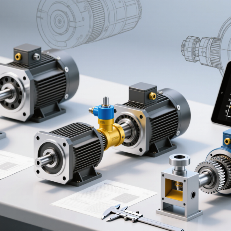
A synchronous gear motor combines a speed-synchronized motor with a gearbox. The rotor follows the rotating magnetic field, so its speed is linked to supply frequency and motor pole count. That matters. The gearbox lowers output speed and increases available torque, making controlled, steady movement practical in compact equipment. But it cannot provide unlimited force: an excessive load may stall the motor or disrupt its motion.
These motors suit mechanisms that need repeatable, relatively slow rotation, such as appliance timers, display turntables, small valves, and light-duty conveyors. Picture a tray turning at a steady pace or a valve moving through a set angle. For selection, check supply voltage and frequency, output speed, starting torque, duty cycle, and gearbox ratio. Also consider shaft loading, mounting space, noise, and temperature around the motor. A gearbox can introduce backlash, which may affect positioning. Easy to overlook. If the application starts under load or changes direction often, verify those conditions against the motor’s specifications; a synchronous design may not be the best fit. Real operating loads can be less tidy than a test bench suggests.
Start with the machine’s actual motion requirement: output speed, direction, and acceptable variation. A synchronous motor’s speed depends on supply frequency and pole count, while the gearbox sets the output speed. Check the motor’s rated conditions and calculate the required gear ratio. Measure the driven load in operation if possible. A conveyor moving small cartons may need steady, low-speed rotation; an indexing table may need brief starts and precise stops. Those are different jobs.
Estimate running torque, starting torque, and load inertia separately. Include friction, belt tension, and any force needed to lift or accelerate the load. A motor that handles steady rotation may stall during startup. Leave a sensible torque margin, but avoid oversizing without reason: excess capacity can add cost and may affect control. Measure it.
Define the duty cycle in real terms: minutes running, pauses, starts per hour, and daily operating time. Frequent starts or long runs can raise motor and gearbox temperatures. Record the ambient temperature and mounting position, then check the supplier’s ratings against those conditions. A spreadsheet is useful, but it can miss a sticky bearing or a load that changes through the cycle. Test with the actual mechanism when practical, and revise the estimate if measured current, temperature, or speed differs from expectations.
Choosing a synchronous gear motor starts with the motion you need. A line-powered synchronous motor runs at a speed tied to supply frequency, while a stepper suits controlled positioning and a brushless DC motor offers adjustable speed. Gearbox type matters, too. Spur gears are compact; helical gears often run more smoothly; worm gears can provide high reduction in a small space, but may lose more energy as heat.
A gear ratio changes speed and torque together. For example, a 10:1 reduction turns a 60-rpm motor output into roughly 6 rpm. Output torque may approach ten times the input torque, minus gearbox losses. Check rated torque, starting torque, voltage, frequency, duty cycle, operating temperature, and permitted load. A motor that handles a brief start may still overheat during continuous operation. Small detail, big consequence.
Efficiency deserves a closer look. The U.S. Department of Energy’s Improving Motor and Drive System Performance: A Sourcebook for Industry estimates that motor-driven systems use about 68% of U.S. industrial electricity. That figure covers many motor applications, not synchronous gear motors alone, but it shows why efficiency and load matching matter. Compare rated efficiency and no-load power where available. I would also check noise and backlash in the actual assembly; catalog numbers do not always reveal how a mechanism behaves after installation.
The chart shows theoretical output speed for a 1,500 rpm, four-pole synchronous motor supplied at 50 Hz. Output speed is calculated as motor speed divided by the reduction ratio.
Selection note: Higher reduction ratios produce lower output speeds and typically greater available output torque. Confirm required torque, gearbox efficiency, duty cycle, and load conditions against the motor’s specifications; actual performance depends on the selected unit.
How to Choose the Best Synchronous Gear Motor in 2026
Choose a synchronous gear motor by matching its speed, torque, and duty cycle to the actual load. A conveyor starting under a full box load needs different torque from a lightly loaded display turntable. Check efficiency across the expected operating range, not only at peak performance. The U.S. Department of Energy’s Improving Motor and Drive System Performance sourcebook reports that motor-driven systems use about 70% of industrial electricity. That figure covers industrial systems broadly, but it shows why small efficiency differences deserve attention.
Compatibility starts with voltage, frequency, mounting dimensions, shaft orientation, and control method. Confirm these against the machine drawing before ordering. For reliability, review rated duty, ambient temperature, enclosure protection, and allowable starts per hour. A spreadsheet can miss vibration, heat buildup, or an awkward mounting position. Test a sample under real load when practical. For 2026 procurement, check which regional requirements apply and consult IEC 60034-30-1 for relevant motor efficiency classifications; its scope does not automatically cover every geared assembly.
Tips: Record load, speed, and daily run time before comparing quotes. Ask for test conditions behind efficiency claims. Keep a little room for uncertainty; field conditions rarely match a perfect datasheet.
A synchronous gear motor should be checked against the actual mechanism, not just its catalog rating. Record supply voltage, frequency, required speed, starting load, duty cycle, and ambient temperature before comparing candidates. Calculate output-shaft torque, including friction, acceleration, and load changes during normal operation. A safety margin matters, but an oversized motor can waste space and complicate control. Numbers can mislead.
Test the candidate on a representative fixture. Measure speed, current, noise, and casing temperature under both steady and changing loads. Run it through repeated starts and stops; a motor that performs well once may behave differently after an hour. Check whether the output speed stays within your tolerance as the unit warms. Keep the test conditions and instrument readings, even when results look ordinary. Small variations are worth investigating.
Review the supplier’s technical data, test methods, and documentation for the exact motor configuration. Ask for torque-speed curves, temperature limits, gear backlash, and evidence supporting stated life estimates. Confirm that samples and production units use the same materials and specifications. A polished datasheet is not proof. I would also check how clearly the supplier responds to specific questions; vague answers can leave real gaps. No review replaces your own application testing.
It pairs a motor that follows the supply frequency with a gearbox. The gearbox reduces speed and increases output torque. That matters.
Motor speed depends on supply frequency and pole count. The gearbox then sets the slower output speed. Check both ratings.
It can suit appliance timers, display turntables, small valves, and light-duty conveyors. Picture a tray rotating steadily or a valve moving through a set angle.
Consider running torque, startup torque, and load inertia separately. Include friction, belt tension, and any lifting force. A motor may handle steady motion but stall at startup.
Record running time, pauses, starts per hour, and daily use. Frequent starts or long runs can raise motor and gearbox temperatures. Test it under load.
Match voltage, frequency, mounting dimensions, shaft orientation, and control method to the machine. Also check ambient temperature, enclosure protection, and mounting position. Drawings can miss awkward details.
Yes. Backlash can reduce positioning accuracy, especially when motion reverses. Check the gearbox specifications if the mechanism needs repeatable stops.
Compare efficiency under expected operating conditions, not just peak performance. Ask how tests were performed, and check applicable regional requirements. Real machines are messier than datasheets.
Choosing the best Synchronous Gear Motor in 2026 starts with understanding how synchronous motion and gear reduction work together. These motors can suit applications that need predictable speed and controlled movement, but the right choice depends on the equipment and operating environment. Define the required output speed and torque, the load’s starting and running demands, and how often and how long the motor will operate. These details provide a practical basis for comparing motor designs and gear ratios.
Next, assess performance specifications alongside efficiency, mounting and electrical compatibility, reliability, and applicable 2026 standards. Check that the selected gear ratio can meet the application’s requirements without exceeding the motor’s limits. Before making a final decision, verify calculations against real operating conditions, review test results, and examine the supplier’s technical documentation and support. A systematic comparison helps ensure the motor is suitable not only on paper but also for dependable operation in its intended application.